Channel ide what. Primary channel ide. How to enable Ultra DMA mode, disable PIO. Hardware Interrupts loads the system
Hello to all blog readers. In this article, we will talk about how to restore system performance. Often users have the problem of a very slow computer, especially when recording and at reading disks, or simply unreasonable "brakes" of the system during operation or loading. Why the system freezes read
There can be a great many reasons for this, today I propose to consider a fairly common one - this is the wrong mode of operation CD/DVD - ROM or hard drives, i.e. let's talk about PIO and DMA.How to check the hard drive for errors and fix them read
What is the essence and difference between PIO and DMA.
PIO and DMA- these are two modes of operation of hard drives, in the general case of any drive.
PIO (Programmable Input/Output)- already outdated mode, it needs to work
engage CPU, resulting in a significant loss of performance.
DMA (Direct Memory Access)- a modern method that bypasses the processor and
draws directly to random access memory, this makes it possible to significantly increase productivity and get rid of annoying "brakes".
DMA mode in various versions has long been used in Windows 7, 8, and 10 operating systems, however in Windows XP,
a situation often occurs in which DMA automatically switches to PIO and it will not work to bring it back by conventional methods. What is causing this situation?
Implemented in Windows XP mechanism error control, if errors occur too often when reading from a hard disk or other drive, the system automatically switches to a slower mode, where their percentage is less. However, Windows XP can transfer a normally operating device to this mode.
How to fix errors
Windows read
And so, let's check the operating modes of all drives so that the system does not slow down ..
1 . Launching the console "Computer Management"– right click on the "My computer"

in the drop-down menu, select the item "Device Manager", or through
Control Panel. Or Start - Run - devmgmt.msc
2. Choose " Device Manager", choose IDE ATA/ATAPI controllers,

several lines with controllers will open - we are interested in :
Primary and Secondary channels IDE→ go one by one to properties these channels (right-click on the channel, line " Properties”), to the bookmark “ Extra options",
there are two groups here "Device 0" and "Device 1", each has lines
"Transfer Mode"- must be selected "DMA if available”, then the line "Current Transfer Mode", should be something like "Ultra DMA mode: 4,

if "PIO mode" is set here, then this is just our case and we will fix it.
If everywhere worth mode ultra DMA, then you are all right and you can not continue further actions.
3. To begin with, let's try to fix it manually - in each line "Transfer mode" set "DMA, if available", press "OK" and restart the computer. After switching on again
we look at the operating modes of the channels, if DMA is everywhere, then everything is in order, if PIO remains, then we continue on.
4. Find again Primary and Secondary IDE Channels and delete them (right-click on each channel, in the list select "Delete"). Don't be afraid, everything will work fine.
Restart your computer again - Windows XP will find controllers and put them into fast mode, i.e. in DMA. Check the result, there should be a mode everywhere DMA.
5. If all of the above did not help and you again see “ PIO mode", then it will be necessary rearrange drivers for the motherboard - reboot
and check the result again.
6. Well, the last point, if after all the suffering the regime PIO never disappeared, then you have to edit in register. I want to note - perform any operations with
registry very carefully and carefully, any wrong action can lead to the complete inoperability of your system. It is best to make a copy of the registry in advance.
How to configure Windows XP using the registry read
First, try disabling the error control system.
To do this, in the registry branch:
HKEY_LOCAL_MACHINE\SYSTEM\CurrentControlSet\Services\Cdfs\,
create a key ErrorControl and set its value to 0.

After that, reboot and follow the step №4.

in it you can manually set the mode DMA.
There are several folders here. - 0000, 0001, 0002.
0000 - responsible for the controller itself;
0001 - responsible for Secondary IDE Chanell;
0002 - responsible for Primary IDE Chanell;
Open the folder for the channel we need. In it are
several keys, to begin with, select:
MasterDeviceTimingModeAllowed
SlaveDeviceTimingModeAllowed
and set the value to 0xffffffff.
After that, we set the value of the following keys:
MasterDeviceTimingMode
SlaveDeviceTimingMode
according to the following data, depending on
supported UDMA - mode:
UDMA Mode 2 - 0x2010
UDMA Mode 4 - 0x8010
UDMA Mode 5 - 0×10010
UDMA Mode 6 - 0xffff
After that, reboot and check the result - everything should work fine.
How to speed up and restore the performance of Windows 10, read
What is the speed of information transfer in computers, read
I hope this article will help you set the modes correctly. PIO and DMA and improve overall system performance.
Occasionally I come across user complaints that the CD / DVD drive has become very slow to burn discs. Sometimes the recording time of a disc reaches an hour and a half instead of the prescribed 5-10 minutes! Moreover, the situation is the same when trying to burn with any programs (starting with Nero, ImgBurn or Astroburn and ending with the standard CD burning wizard) and on any discs.
The most common reasons for this situation are cheap low-quality discs, on which something was previously tried to be written or read. The fact is that Windows (more precisely, the Atapi.sys driver) has the ability to independently choose one of several high-speed modes of operation with the drive. So, when a large number of read / write errors appear, Windows automatically switches the connection speed to the drive from the fastest data exchange mode DMA to slow but more reliable PIO
It's easy to deal with this.
To do this, you need to open Device Manager» by going to the menu « Start» -> « Control Panel«->» System» -> bookmark « Equipment» -> click on the button « Device Manager«.
Or, if the desktop has an icon " My computer"- click on it with the right button and in the menu that appears, left-click on the item" Properties". Well, then again the bookmark " Equipment” and click on the button “ Device Manager«
Open ‘Device Manager’
Then find the item in the list IDE ATA/ATAPI controllers and expand the list of controllers by clicking on the plus sign to the left of it.
There must be at least two items:
- Primary IDE channel
- Secondary IDE channel
 And now - the properties of the primary and secondary channels of the IDE controller
In the properties of both channels, the tab “ Extra options«
So. Wherever in the field Current transfer mode” it says “Ultra DMA *** mode” or “PIO” put in the field “ Transfer mode" option " DMA if available«.
After checking both channels, close all open windows with the buttons "OK" and restart your computer.
If it didn't help.
If it so happened that this did not help - do not despair!
Do everything as described above, but when you right-click on the items " Primary, Secondary IDE channel"Choose not the item "Properties", but " Delete«!
 Deleting a channel
When asked if you are sure - feel free to click " Yes«.
 Confirm deletion
These actions will cause the system to re-detect the characteristics of both channels after a reboot and adequately assess the connection speed to the device.
By the way, in Windows 7 you can still try Disable", but not " Delete» channels without DMA
How to enable Ultra DMA mode, disable PIO. Hardware Interrupts loads the system
Hardware Interrupts How to enable Ultra DMA mode
2. Disable error control .
HKEY_LOCAL_MACHINE\SYSTEM\CurrentControlSet\Control\Class\<4D36E96A-E325-11CE-BFC1-08002BE10318>.
In the same sections, check
0x10010 - corresponds to UDMA Mode 5 (ATA100).
0x8010 - UDMA Mode 4 (ATA66).
0x2010 - UDMA Mode 2 (ATA33).
0x0410 - Multi-Word DMA Mode 2
But, if you don’t know exactly what mode the screw should work in and if you did everything correctly, but nothing has changed after the reboot (unlikely, but suddenly ...), then
In this case, first remove the IDE controller from the list of devices, and reboot. Windows will re-find and reinstall the IDE controller driver, and all devices will enter the required DMA modes (MasterDeviceTimingMode and SlaveDeviceTimingMode will automatically take the desired value).
Now about the Hardware Interrupts process - the process of interrupting the hardware itself. When a hard drive is bad, it constantly reports read errors, and these interruptions are obtained. The processor starts to fix these errors, and not your task, and the brakes begin.
This is possible and not only through the hard drive. You can try to change the interrupt numbers in the BIOS, but that's a different story.
I explain with my fingers. Do you see the middle one?
If the hard drive suddenly began to slow down. Spontaneous activation of PIO mode and how to deal with it
The hard drive is connected to the motherboard with a cable. This cable essentially connects the hard drive electronics to the disk controller on the motherboard. Cable type (IDE, SATA, .) does not matter. Yes, each type of cable has its own physical limitations on data transfer, but this only indicates what kind of data stream the hardware was sharpened at its ends.
The disk controller can work with disks in several different modes. The hard drive electronics, in turn, also supports different modes of operation with a disk controller. The drive/controller mode sets may not match, and most often they do.
By default, the operating system selects the fastest mode of operation that both the controller and the disk support at the same time.
For many, game analogies are clearer, so I will use one of them.
Everyone knows that 3D can be software (Software Rendering) and hardware (Direct3D, OpenGL).
In software 3D, each frame is calculated by the processor, and the video card is only responsible for displaying the resulting image on the screen. 3D renders use a wild amount of math, which puts a lot of strain on the CPU, while producing mediocre results. Why is this happening? The fact is that the Central Processing Unit (CPU) is universal, that is, it is adapted for absolutely different kinds of calculations. Three-dimensional computing is only a narrow class of tasks that the CPU is capable of performing. And it turns out that the universal CPU does not work optimally with graphics.
In the case of hardware 3D, the processor throws primitives (textures, models, etc.) into the video card and gives commands for their processing, and the card itself does the scene building and beautiful effects - with the help of its own special graphics processor (GPU, GPU), sharpened just for such tasks. Calculations on it are noticeably faster, while the central processor is not loaded.
So, PIO is a type of software 3D: all disk work is done through the CPU. Very slow and resource intensive.
And DMA is hardware data processing that uses all sorts of "accelerators". If only they were supported by the controller and the disk itself.
Windows works with disks in DMA mode. Well, usually.
Under certain conditions (for example, if several specific read-write errors occur), Windows switches the disk mode to PIO. Immediately, tightly and without the possibility of rehabilitation.
After that, it is impossible to force the system to work with the disk in DMA mode using standard methods.
About non-standard - a little lower.
Symptoms that Windows has switched work with the hard drive to PIO mode
- The system began to slow down terribly on disk operations. The speed of working with the disk fell by 2-3 times.
- For disk operations cpu is overloaded. In the Windows Task Manager, the System process (or the Interrupts process in the Process Explorer utility) takes up 80-90% of the CPU time.
- Sharpness and suddenness of what is happening. Just yesterday / 5 minutes ago the system worked as usual, but here it is on you.
In modern realities, when hard drives are the slowest computer devices, a "bottleneck" that slows down the work of programs - even a twofold drop in their speed can be catastrophic.
We make sure that Windows has switched work with the hard drive to PIO mode
Open the "Device Manager" in the "Management Console" of the computer.
RMB to "My Computer" (on the desktop or in the Start panel, it doesn't matter) → "Management".
We open the disk controller branch in the tree (“IDE ATA / ATAPI controllers”) and find the channel to which our screw is connected.
Press RMB → "Properties" (or just double-click with the left mouse button)
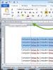
If the “Transfer Mode” is set to “DMA if available”, and in fact the hard drive is operating in PIO mode (see the picture below), then everything is bad, and this is our case.
To correct the error, it is enough to remove the disabled device and install it again. You can do this from the same "Device Manager".
Or we climb into the register.
In the registry ("Start" → "Run" → regedit) you need to go to the branch at:
0000 - settings of the controller itself.
0001 - Primary channel settings (Primary IDE Chanell).
0002 - secondary channel settings (Secondary IDE Chanell).
MasterDeviceTimingModeAllowed
- the maximum speed mode in which the main (Master) device in the channel is allowed to operate. Essentially, the key value is a binary mask. Restricts the selection of "Transfer Modes" from the dialog box.
MasterDeviceTimingMode
- current operating mode of the main device in the channel. Corresponds to the Current Transfer Mode setting in the dialog box.
The same keys starting with Slave and not Master are valid for the slave device in the channel:
If the "Device type" dialog box was selected manually, the corresponding settings are stored in keys with the User prefix:
- UserMasterDeviceTimingModeAllowed
- UserMasterDeviceTimingMode
- UserSlaveDeviceTimingModeAllowed
- UserSlaveDeviceTimingMode
The value of any key [. ]DeviceTimingModeAllowed must be 0xffffffff . This means that the selected device can operate in any data transfer mode, without restrictions.
If the key value is 0x00000001f (HEX 1f), then the device can only work in PIO mode.
Change the value of the desired [. ]DeviceTimingModeAllowed to "ffffffff" and reboot.
Operating mode codes:
0x0000001f - PIO
0x00000410 - Multi-Word DMA Mode 2 and PIO 4.
0x00002010 - UDMA Mode 2 (ATA33).
0x00008010 - UDMA Mode 4 (ATA66). To enable, you can use the mask "0x0000ffff"
0x00010010 - UDMA Mode 5 (ATA100). To enable, you can use the mask "0x000fffff"
ATA/ATAPI versions (.4,5,6.) are versions of the ATA/ATAPI specification approved by the X3T13 committee. And PIO (Programmed Input-Output) and DMA / UDMA are data transfer modes. One has nothing to do with the other. PIO modes imply the mandatory involvement of the CPU when transferring data - when reading data from the media, the CPU reads them from the controller port (the IN command of the processor), while writing, the CPU writes to the port (the OUT command). In DMA (UDMA) modes, the CPU only initializes the transfer (and preliminarily also the DMA controller) - the rest of the work is done by the DMA controller (Direct Memory Access) and the IDE controller (in Bus Master mode). It is clear that the latter option is more profitable - less processor load - therefore, after 1995, no one developed PIO modes anymore, and in the specifications approved by ATA / ATAPI (I don't care who suggested what at the X3T13 meetings), PIO-5 never existed. And UltraDMA 44 is UltraDMA 3 - this mode exists, it's just that almost no one uses it (since its support is everywhere where there is UDMA 4 - 66). By the way, ATA/ATAPI-6 has not yet been approved, this document exists in a preliminary version, the so-called working draft, and may still change (but it is unlikely that PIO-5 will be added there). The last one approved is version 5. And UDMA66 appeared with ATA-4, and UDMA100 with ATA-5. The specifications contain recommendations on the use of data transfer modes, and not at all mandatory requirements for their support. There are screws corresponding to ATA-5, but only supporting UDMA66 (eg Quantum Fireball+ LM). And then there are CD-ROMs with UDMA33 support and ATAPI-4 and 5 compliance. Starting with version 4, the ATA and ATAPI specifications have been merged into one document.
This happens if XP detects that the device is not stable in its selected mode. This is determined by the number of read errors received from the drive. This usually means that the drive is in a bad state, and the truth is that it should be retired. But it is a pity to throw away a seemingly working drive, so such devices can be found in the cars of our readers. Although, thanks to error control mechanisms, many such drives can work happily and without problems for a long time, despite the opinion of XP about them. The only thing that spoils the blood of their owners is the constant brakes of the system, due to the PIO mode. I'm not completely sure how XP's error control system works and is managed, so I can't guarantee that this advice will work in all cases. But you can try.
To disable the error tracking mode, you can try setting the ErrorControl key located at HKEY_LOCAL_MACHINE\SYSTEM\CurrentControlSet\Services\Cdfs\ to 0
Open the Device Manager window
Option I:
1.
Right-click on the "My Computer" icon.
2.
In the drop-down menu, select the "Management" item with the left mouse button.
3.
The "Computer Management" window will open, where in the list on the left you need to select (press once) "Device Manager" with the left mouse button, after which the "Device Manager" will be available on the right side of this window.
Option II:
1.
On the desktop at the bottom left, click on the "Start" button once, and then go to the "Control Panel" in the drop-down menu.
2.
In the opened window (or menu) "Control Panel" double-click the left mouse button (or click once) on the "System" icon.
3.
In the System Properties window that opens, select the Hardware tab.
4.
In the System Properties window, on the Hardware tab, click the Device Manager button.
Check the modes of operation of IDE channels
1.
In the "Device Manager" window, open the "IDE ATA / ATAPI Controller" item (Click on the "+" button opposite the "IDE ATA / ATAPI Controller" item or double-click on this item.
2.
Right-click once on the item "Primary IDE Channel" and in the drop-down menu, left-click once on the item "Properties".
3.
In the "Properties: Primary IDE Channel" window that opens, select the "Advanced Options" tab.
4.
On the "Advanced Options" tab, in the "Device 0" and "Device 1" areas, the "Transfer Mode:" line should be set to "DMA, if available." If the line "Transfer mode:" is set to "Only PIO", then you need to set "DMA, if available" (select from the drop-down list on the right) and click the "OK" button.
5.
Repeat steps 2) - 4) for "IDE ATA/ATAPI Controller" "Secondary IDE Channel" in the "Device Manager" window.
6.
After the performed operations, it is necessary to restart Windows. After rebooting, check the modes of operation of the IDE channels. If, after the performed operations, the “Transfer mode:” line is still set to “PIO only”, then the incorrect motherboard drivers are installed on your computer. In this case, you need to install the "native" drivers of the motherboard, and then enable the DMA mode.
In case of problems with the performance of the hard drive, you must first clean the hard drive of debris, then defragment and at the very end check HDD for errors, your "screw" can also slow down due to bad sectors (bad blocks), also read our articles: What are bad sectors and how to remove them using the HDDScan program.
They brought a computer and complain about low performance, tried to reinstall the operating system, it doesn’t help, the components are not of the last century, it should work for a solid four, only one thing but ...
The first thing I would pay attention to is the correct connection of jumpers on hard drives, but we have a separate article about this “Jumpers on a hard drive”, you can read it, but we had a different problem.
Sometimes two IDE devices are connected not quite correctly, for example, a hard disk is connected to one IDE connector on the motherboard using a cable as a Master device and CD / DVD as a device (Slave).
Many can say what is right, because the hard drive is more important, yes it is, but the drive almost always works slower than the hard drive, and they are connected by one cable. So the IDE controller switches both devices to a slower drive mode, in our case it was just that. If you are dealing with an old configuration, it is always better to connect the hard drive separately from the drive, to a separate cable.
The same applies to two hard drives connected to the same cable, they both must support the fastest data transfer mode. If one hard drive is slower and operates in Ultra ATA/100 mode, then another faster one, designed to operate in Ultra ATA/133 mode, will operate at the speed of the slow Ultra ATA/100.
I start the computer, go to the device manager, then IDE ATA / ATAPI controllers, select the item Primary IDE channel, double-click on each channel with the left mouse button and go to the Advanced settings tab. I see that the drive, together with the hard drive, works in PIO mode, no more, no less, that's how it happens, of course, the hard drive will slow down.

I had to buy an additional IDE cable and connect each device to the motherboard separately. I also had to change the drive, not quite old, but apparently not working, it worked only in PIO mode, even on another computer, we never did anything with it. By the way, an interesting example is given in our article PIO and DMA
PIO (Programmable Input / Output) is a rather outdated mode of operation of devices; when working, it uses the central processor, which undoubtedly reduces performance.
DMA (Direct Memory Access) is a mode in which a hard disk or disk drive directly accesses RAM, which of course increases performance by several times.
- Of course, DMA mode is preferable, but sometimes with frequent hard disk read errors, Windows XP switches DMA mode to PIO. And the question arises, how to enable DMA mode? First of all, let's try to set the "Transfer Mode" item to the "DMA, if available" mode, then "OK" and reboot. The computer has booted up, we go to the Device Manager and see the Transfer mode, DMA is everywhere, so everything worked out for us, if not, we try another method.
- You need to reinstall the drivers on the motherboard, this also sometimes helps.
- You must use an 80-wire cable to connect this device, also try changing the IDE cable or connect the hard drive to another connector on the motherboard, after inspecting it for bent pins.
- To return the DMA mode, you can use the registry, you need to disable the error control system and manually set the DMA mode, but this method is best used last, you can read PIO and DMA in our article, and now let's try point #5 first.
- We delete the Primary and Secondary IDE channels, move the mouse over them, right-click and select delete, reboot again, the operating system should find the controllers and put them in DMA transfer mode.
Other identical option names: IDE Channel 0 Master, Primary Master.

The BIOS has several options for configuring hard drives and other internal storage devices (drives). The Primary IDE Master option is one of the most commonly used of its kind.
As a rule, before the advent of the SATA interface, the motherboards of most personal computers supported only IDE interface drives. Typically, the user could install no more than 4 drives - hard drives or CD / DVD drives. Two of them can be located on the primary IDE channel (Primary), and the other two on the secondary channel (Secondary). In each of these two pairs of drives, one drive is the Master and the other is the Slave. Thus, in total, the BIOS, as a rule, has four options for configuring drives:
- Primary IDE Master
- Primary IDE Slave
- Secondary IDE Master
- Secondary IDE Slave
Each IDE channel is a connector that connects to an IDE data cable, which in turn has three connectors. One of them is designed to connect to the IDE connector on the motherboard, the other two are for connecting drives. The choice of which category the drive will belong to - to the Master or Slave category, is determined solely by the installation of jumpers on the drives, which must be carried out in accordance with the instructions attached to the drive.
In the parameter, you can see a number of sub-options that can define the type of drive, its characteristics, capacity and some operating parameters.
The most important of these options is the Type option. As a rule, it can take the following values:
- Auto – drive type is detected automatically
- User - the user can set the drive type manually
- CDROM - the drive is a CD/DVD drive
- ZIP - Drive is an Iomega ZIP type device
- LS-120 - the drive is an LS-120 type device
- None - this device is not used
Also in this option, you can sometimes select a predefined type of drive, indicated by some number, for example, from 0 to 50.
If the user selects the User value, then he will have to specify the characteristics of the hard disk, such as the number of heads, cylinders, and sectors.
The following additional options are also often found:
- LBA Mode
- IDE HDD Block Mode or Multi-Sector Transfers (Block Mode)
- Programmed I/O Modes
Typically, after a drive is connected and the computer boots up, the BIOS will automatically set the Type option for the drive to Auto. This means that the BIOS automatically detects all drive parameter values and does not require manual configuration.
The vast majority of IDE drives support auto tuning. The only exceptions may be very old drives, occasionally found in ancient computers, which may require manual setting of the number of heads, cylinders and sectors.
The LBA Mode option requires some explanation. This option is to enable the addressing mode used by hard drives larger than 504 MB. If you are using a smaller hard drive, then you must disable this option. For the rest of the settings, it's best to leave the default values.
A useful blog for novice computer users and not only ..
How to restore system performance, PIO and DMA modes

Hello to all blog readers. In this article, we will talk about how to restore system performance. Often users have the problem of a very slow computer, especially when recording and at reading disks, or simply unreasonable "brakes" of the system during operation or loading. Why the system freezes read here
There can be a great many reasons for this, today I propose to consider a fairly common one - this is the wrong mode of operation CD / DVD - ROM or hard drives, i.e. let's talk about PIO and DMA. How to check the hard drive for errors and fix them read here
What is the essence and difference between PIO and DMA.
PIO and DMA- these are two modes of operation of hard drives, in the general case of any drive.
PIO (Programmable Input/Output)- already outdated mode, it needs to work
engage CPU, resulting in a significant loss of performance.
DMA (Direct Memory Access)- a modern method that bypasses the processor and
draws directly to RAM, this allows significantly increase productivity and get rid of annoying "brakes".
DMA mode in various versions has long been used in Windows 7, 8, and 10 operating systems, however in Windows XP, a situation often occurs in which DMA automatically switches to PIO and it will not work to bring it back by conventional methods. What is causing this situation?
Implemented in Windows XP mechanism error control, if errors occur too often when reading from a hard disk or other drive, the system automatically switches to a slower mode, where their percentage is less. However, Windows XP can transfer a normally operating device to this mode.
How to fix errors Windows read here
And so, let's check the operating modes of all drives so that the system does not slow down ..
1 . Launching the console "Computer Management"- right click on "My computer"

in the drop-down menu, select the item "Device Manager", or through
Control Panel. Or Start - Run - devmgmt.msc
2.
Choose " Device Manager", choose IDE ATA/ATAPI controllers,

several lines with controllers will open - we are interested in :
Primary and Secondary channels IDE→ go one by one to properties these channels (right-click on the channel, line " Properties”), to the bookmark “ Extra options",
there are two groups here "Device 0" and "Device 1", each has lines
"Transfer Mode"- must be selected "DMA if available”, then the line "Current Transfer Mode", should be something like "Ultra DMA mode: 4,

if "PIO mode" is set here, then this is just our case and we will fix it.
If everywhere worth mode ultra DMA, then you are all right and you can not continue further actions.
3.
To begin with, let's try to fix it manually - in each line "Transfer mode" set "DMA, if available", press "OK" and restart the computer. After switching on again
we look at the operating modes of the channels, if DMA is everywhere, then everything is in order, if PIO remains, then we continue on.
4.
Find again Primary and Secondary IDE Channels and delete them (right-click on each channel, in the list select "Delete"). Don't be afraid, everything will work fine.
Restart your computer again - Windows XP will find controllers and put them into fast mode, i.e. in DMA. Check the result, there should be a mode everywhere DMA.
5.
If all of the above did not help and you again see “ PIO mode", then it will be necessary rearrange drivers for the motherboard - reboot
and check the result again.
6. Well, the last point, if after all the suffering the regime PIO never disappeared, then you have to edit in register. I want to note - perform any operations with
registry very carefully and carefully, any wrong action can lead to the complete inoperability of your system. It is best to make a copy of the registry in advance.
How to configure Windows XP using the registry read here
First, try disabling the error control system.
To do this, in the registry branch:
HKEY_LOCAL_MACHINE\SYSTEM\CurrentControlSet\Services\Cdfs\,
create a key ErrorControl and set its value to 0.

After that, reboot and follow the step №4.
All of them are part of the southbridge of the chipset, and the parameters for configuring them are usually located in the section Integrated Peripherals. The number of options available in this section depends on the number of certain peripheral devices in a particular motherboard model.
There are usually options in Integrated Peripherals that disable many peripherals, and if the operating Windows system does not find any of them, you should check if it is disconnected using the BIOS.
You can also force unused devices to turn off, thus freeing up some system resources, and change the settings of some devices.
In chapter Integrated Peripherals all parameters can be in the form of a long list, or divided into several categories. In BIOS versions with a horizontal menu bar (boards manufactured by Intel, ASUS, ASRock), look for a subsection with this name in the menu Advanced.

Configuring IDE Controller Modes in Windows
The parameter controls the first IDE channel. After it is disabled, the settings for the PIO and UDMA modes, as well as the drive parameters in the section Standard CMOS Features.
1. Enabled (On) - the first IDE channel is enabled;
2. Disabled (Off) - the first IDE channel is disabled and does not use system resources; this can be done if there are no drives connected to this channel.
The parameter is similar to the previous one, but enables or disables the second IDE channel.
The parameter controls the IDE channel in the same way as OnChip IDE Channel 0/1, but has different meanings:
2. Secondary - only the second IDE channel is enabled;
3. Both - both IDE channels are enabled;
4. Disabled - both IDE channels are disabled.
There are usually four such parameters - one for each of the drives that can be connected to the first or second IDE channel. Use them to select one of the software input/output (PIO) modes to be used by the device. PIO mode is rather slow today and is used by very old hard drives or CD-ROM drives. Modern IDE devices operate in the faster UDMA mode, which will be discussed later.
1. Auto - the desired mode is set automatically; this is the default value and it is recommended to select it;
2. Mode 0-4 - forced installation of one of the PIO options: Mode 0 is the slowest and corresponds to a data transfer rate of 3.3 Mbps, and in the fastest Mode A, the maximum speed is 16.6 Mbps.
You need to specify the PIO mode manually only when the device does not support UDMA and the BIOS cannot correctly configure it with the Auto value. If you select a too slow PIO mode, all the capabilities of the connected device are not used, if it is too fast, errors may occur during data transfer.
These options enable or disable the use of UDMA (UltraDMA) mode for each IDE device. It is faster than PIO and has several implementations that differ in maximum speed: UDMA 33, UDMA 66, UDMA 100, UDMA 133. To use UDMA 66 and higher, a special 80-wire cable is required, and for UDMA 33 and all modes PIO will fit any cable.
1. Auto - UDMA mode is enabled; speed will be selected automatically depending on the maximum speeds of the controller and drive; if data exchange in UDMA mode is not possible, the system will automatically switch to PIO mode;
2. Disabled - UDMA mode is disabled, while data between the controller and the drive will be exchanged only in PIO mode. This value can be set if there are problems connecting legacy IDE devices.
Modern operating systems can manage such modes themselves. For example, to find out the current mode of operation of IDE devices in Windows XP/Vista/7, open Device Manager, expand the node in the list of devices IDE ATA/ATAPI controllers, double click on the primary or secondary link icon IDE and go to the tab Extra options. Here you can find out what data exchange mode the devices are currently using, as well as change the mode of operation from UDMA to PIO or vice versa.
The parameter enables or disables the use of direct memory access (DMA) mode for all IDE hard drives.
1. Enabled (On) - DMA mode is enabled;
2. Disabled (Off) - DMA mode is not used.
The parameter controls the block mode of operation of the IDE controller, in which the data exchange speed is increased due to the transfer of several sectors with data at once. All modern hard drives support block mode, so it's best to leave it enabled.
1. Enabled (On) - block mode is enabled, the optimal block size will be selected automatically;
2. Disabled (Off) - block mode is disabled.
This option enables or disables prefetching of data by the IDE controller.
1. Enabled (On) - the prefetch mode is enabled, which increases the speed of data exchange; installed by default;
2. Disabled (Off) - prefetching is not used; you can try this option if your hard drive is experiencing errors.
With this setting, you can improve the performance of your hard drive by making more efficient use of the cache memory in the drive. It also reduces the time delays between individual read or write cycles.
1. Enabled (On) - Burst Mode is enabled;
2. Disabled (Off) - Burst Mode is not used.
With this option, found in some BIOS versions, you can specify the type of cable used for IDE1 or IDE2 channels.
1. Auto - cable type is automatically detected by the BIOS;
2. ATA66/100 - uses an 80-wire cable that allows you to work in ATA66/100 mode;
3. ATAZZ - a 40-core cable with the maximum allowable ATAZZ mode is used.
1. Open Device Manager.
This can be done by right-clicking on "My Computer" (My Computer), select the tab "Disk devices" (Hardware), and click the button select "IDE" ( Select Device manager).
2. Open the "IDE ATA/ATAPI Controllers" section and double click on "Primary IDE Channel".
3. On the Advanced Settings tab, check the Device 1 setting.
It is possible that your current setting is "PIO".
4. Set "DMA" if available (DMA if available).
5. At the end of all actions, restart the computer.
If you have a device on a secondary IDE channel, repeat the same steps for the Secondary IDE Channel.
Kaspersky Lab warns that a large-scale campaign is underway in Russia to infect Android devices with a dangerous malware called Asacub.
The named malware is a Trojan whose main task is to steal the victim's bank card data.
In addition, Asacub can perform a number of other functions.
In particular, the program is capable of sending information about an infected device and a list of contacts to attackers, calling certain numbers, sending SMS messages with the specified text to a specified number, closing certain applications, etc.
The malware distribution scheme is as follows.
The user receives an SMS from a familiar number with one or another text and an offer to follow the specified link.
When you go to such a site, a Trojan download page opens with instructions on how to install it.
Currently, the number of Russian Android users who receive messages from malware reaches 40,000 per day.
Some Windows 10 users are reporting that the update system offers them the same cumulative September update, but with two separate entries in the update history. We are talking about KB4457128.
According to users, this update contains controls to protect against the Specter processor vulnerability.
It is downloaded, installed, asked to reboot the system, and after that it is again offered for download.
In fairness, we note that this update can be installed again or ignored.
There will be no difference.
But that's not the only problem with updates.
On Tuesday, September 11, the Servicing Stack Update (SSU) for Windows 10 (1803) was released.
And on this day, users are faced with a number of problems.
After turning on the device, they were greeted with a message: “Error. Failed to install SSU before LCU.
Turn off your computer and turn it on again."
SSU is required to install other OS updates.
It also includes the Component-based servicing (CBS) service, which is key to the elements of a Windows deployment. And the LCU (Latest Cumulative Update - the last cumulative update) should have installed all the updates, but this did not happen due to an SSU error.
Finally, Microsoft managed to spoil the blood of the testers.
On Wednesday, September 12, Microsoft released Windows version 10 19H1 (18237) for members of Skip Ahead's internal testing program.
During installation, error 0x800700e appeared, and RAM consumption also increased.
It turned out that the update was sent in encrypted form.
But the problem with the RAM has not yet been solved.
The computer is very slow, it is not possible to work at all. At the same time, the HDD access indicator is constantly blinking, the task manager shows CPU usage, but there is no movement? If you enable a third-party manager, such as Process Explorer, you can see that the process Hardware Interrupts loads the system by 50% or more. Most likely your hard drive has gone into PIO mode. This means that when reading from a disk, after 6 timeout errors, Windows switches the connection speed of the IDE / ATAPI (HDD) controller from fast UDMA mode to slow PIO and everything starts to slow down. How to re-enable Ultra DMA mode?
How to enable Ultra DMA mode
1. To find out what mode the screw is in, go to the device manager - IDE / ATAPI controllers - primary (secondary) channel and in the additional parameters look at the transfer mode - if PIO, then it slows everything down and the Hardware Interrupts process loads the processor (I have was 40-50%). We are trying to set the “DMA if available” mode (and do this in all primary and secondary channels) and reboot the system. A little work and check again the IDE / ATAPI controller mode. If the PIO mode is set again, then check the hard drive cable and power supply. If it doesn’t help, then the solution is simple - change the hard drive or option 2:
2. Disable error control .
We go into the registry (menu Start-Run-regedit), then in the section
In subsections 0001 and 0002, we do this:
1. On the Edit menu, New, DWORD option.
2. Type the string ResetErrorCountersOnSuccess and press ENTER.
3. Double-click on the created parameter and enter the value 1. Click OK.
In the same sections, check
Next, check that in the same sections the MasterDeviceTimingModeAllowed and SlaveDeviceTimingModeAllowed parameters have the value ffffffff (in hexadecimal system). And assign one of the values to the corresponding MasterDeviceTimingMode or SlaveDeviceTimingMode parameter:
0×10010 - corresponds to UDMA Mode 5 (ATA100).
0x8010 - UDMA Mode 4 (ATA66).
0x2010 - UDMA Mode 2 (ATA33).
0x0410 - Multi-Word DMA Mode 2
Reboot the system. That's all! In theory, you should always have Ultra DMA mode.
But, if you don’t know exactly what mode the screw should work in and if you did everything correctly, but nothing has changed after the reboot (unlikely, but suddenly ...), then in this case, first remove the IDE controller from the list of devices, and reboot. Windows will re-find and reinstall the IDE controller driver, and all devices will enter the required DMA modes (MasterDeviceTimingMode and SlaveDeviceTimingMode will automatically take the desired value).
After that, climb into the registry and do all the steps, except for changing the MasterDeviceTimingMode and SlaveDeviceTimingMode parameters, and reboot again. Now everything should definitely work.
Post Views: 1 468
The "original" ATA interface is intended exclusively for connecting HDDs, it does not support features such as the ATAPI interface for connecting IDE devices that are different from HDDs, i.e. blockmode or LBA transmission mode (short for logical block addressing).
After some time, the ATA standard ceased to meet the growing needs, because. newly released HDDs required a significantly higher data transfer speed, as well as the availability of new features. Thus, the ATA-2 interface was born, soon also standardized by ANSI. While maintaining interoperability with the ATA standard, ATA-2 introduced several additional features:
- Faster PIO Modes. Added support for PIOmodes 3 and 4;
- Faster DMA Modes. Supports multiword DMAmodes1 and 2;
- Block Transfer. Commands have been included that allow transfers in blocktransfer mode to improve performance;
- Logical Block Addressing (abbr.. LBA). ATA-2 requires HDD support for the LBA transfer protocol. Of course, in order to use this protocol, it must also be supported by the BIOS;
- Improved IdentifyDrive command. The interface has increased the amount of information about the characteristics of the HDD issued by system requests.
Everything would be fine, but manufacturers, in their desire to get a larger piece of the market, began to compose beautiful names, calling them interfaces of their HDDs. After all, the FastATA, FastATA-2, and EnhancedIDE interfaces are, in fact, based on the ATA-2 standard, being nothing more than beautiful marketing terms. The differences between them are only in what part of the standard and how they support.
The biggest confusion comes from the names FastATA and FastATA-2, which belong to the smart heads of Seagate and Quantum, respectively. It would be quite logical to assume that FastATA is a kind of improvement on the ATA standard, while FastATA-2 is based on the ATA-2 standard. Unfortunately, everything is not so simple. In reality, FastATA-2 is just another name for the ATA-2 standard. In turn, all the differences between FastATA and it come down to the fact that the fastest modes are supported here, namely: PIO mode4 and DMA mode2. Both companies are attacking Western Digital and its EIDE standard for adding to the confusion. EIDE is also distinguished by its shortcomings, however, about them a little later.
In an attempt to further develop the ATA interface, a draft ATA-3 standard was developed, which focused on improving reliability indicators:
- ATA-3 contains features that increase the reliability of data transfer through the use of high-speed modes, which is a serious problem, because. the IDE/ATA cable has remained unchanged since the birth of the standard;
- ATA-3 includes SMART technology.
ATA-3 was not approved as an ANSI standard primarily because it did not use new data transfer modes, despite the fact that SMART technology is now widely used by HDD manufacturers.
The next round in the development of the IDE / ATA interface is the UltraATA standard (also known as UltraDMA or ATA-33, or DMA-33, or ATA-3 (!)). UltraATA, in fact, is the standard for using the fastest DMA mode, mode3, which provides a data transfer rate of 33.3 MB/s. In order to ensure reliable data transfer over the old cable model, special error control and correction schemes are used. Backward compatibility with previous standards: ATA and ATA-2 is preserved. Thus, if you bought an HDD with UltraATA interface and suddenly found that it is not supported by your motherboard, don't worry - the drive will still work, although somewhat slower.
Finally, the latest achievement in this area is the UltraATA/66 interface, which was developed by Quantum. The interface allows data transfer at a speed of 66MB/s.
During the early development of the IDE/ATA interface, the only device that needed this interface was the HDD. nascent CD-ROM drives and streamers came with their own interface (you probably remember the days when CD-ROMs were connected via an interface on a sound card). However, it soon became clear that the use of a fast and simple IDE/ATA interface to connect all possible devices promises to bring significant benefits, incl. due to versatility. Unfortunately, the command system of the IDE/ATA interface was designed exclusively for HDD, so you can't just connect, for example, a CD-ROM to an IDE channel just like that - it simply won't work. Accordingly, it was necessary to develop a new protocol - ATAPI (abbreviated from ATA Packet Interface). The protocol allows most other devices to connect using a standard IDE cable and "feel" like an IDE/ATA HDD. The ATAPI protocol is actually much more complex than ATA, because data transfer here is using the DMA and PIO modes, while the implementation of support for these modes largely depends on the features of the connected device. The very name packet (from English packet) was received by the protocol due to the fact that the device has to transmit commands literally in groups or packets. From the standpoint of the average user, however, most importantly, there is no distinction between an IDE/ATA HDD, an ATAPI CD-ROM, and a ZIP drive. Today's BIOSes even support booting from ATAPI devices.
Now, as promised, let's move on to EIDE. This term was introduced by WesternDigital. EIDE is quite widely used and almost also widely criticized, in our opinion it is quite deserved. The main reason for harsh criticism is the fact that, in fact, EIDE is not a standard at all, but a purely marketing term, and the content of this term is constantly changing. So, at first EIDE included support for PIO modes up to mode3, then support for mode4 was added. A significant disadvantage of EIDE as a standard is the inclusion of absolutely diverse things in its specification. See for yourself, at the moment EIDE includes:
- ATA-2. Completely, incl. the fastest modes
- ATAPI. Whole;
- Dual IDE/ATA Host Adapters. The EIDE standard includes support for 2 IDE/ATA hosts, so you can use up to 4 IDE/ATA/ATAPI devices in parallel.
Let us now analyze what the phrase "HDD with EIDE interface" means. Since it makes no sense to support ATAPI, and it will not be able to support 2 IDE channels, it all comes down to a modest one: "HDD with ATA-2 interface". The idea, in principle, was not bad - to create a standard that covers the chipset, BIOS and hard drive. However, since most of EIDE as a standard refers directly to the chipset and BIOS, there is confusion between EnhancedIDE and EnhancedBIOS, which appeared around the same time (i.e. BIOS that supports IDE / ATA for HDDs larger than 504MB). It would be quite logical to assume that to use HDDs with a capacity of more than 504 MB, an EIDE interface is required, however, as you already understood, only EnhancedBIOS is needed. Moreover, manufacturers of EnhancedBIOS cards advertised them as "enhanced IDE cards". Fortunately, now these problems are in the past, in other matters, like the 540MB barrier.
To somehow systematize the information, all the main (official and unofficial) IDE interface standards that were described above are given in the form of a table.
|
Standard |
Interface |
DMA modes |
PIO modes |
Differences from IDE/ATA |
|
Singleword 0-2; multiword 0 |
||||
|
Singleword 0-2; multiword 0-2 |
Support LBA, block transfer, mode, improved identify drive command |
|||
|
marketing term |
Singleword 0-2; multiword 0, 1 |
Similar to ATA-2 |
||
|
marketing term |
Singleword 0-2; multiword 0-2 |
Similar to ATA-2 |
||
|
Informal |
Singleword 0-2; multiword 0-2 |
Similar to ATA-2, with added support for transfer reliability at high speeds, SMART technology is used |
||
|
Informal |
Singleword 0-2; multiword 0-3 (DMA-33/66) |
Similar to ATA-3 |
||
|
Singleword 0-2; multiword 0-2 |
Similar to ATA-2, added support for non-HDD devices |
|||
|
marketing term |
Singleword 0-2; multiword 0-2 |
Similar to ATA-2 +ATAPI, supports 2 host adapters |
Smoothly we pass to not less interesting subject. In total, there are 2 parameters that characterize the speed of data transfer when using an HDD with an IDE / ATA interface. The first of them is the internal transfer rate, which characterizes the speed of data transfer between the internal HDD buffer and magnetic media. It is determined by the rotation speed, recording density, etc. Those. parameters that depend not on the type of interface, but on the design of the carrier. The second indicator is the external data transfer rate, i.e. data transfer rate over the IDE channel, completely dependent on the data transfer mode. At the very beginning of the use of IDE / ATA disks, the speed of the entire disk subsystem depended on the internal data transfer speed, which was much less than the external one. Today, due to the increase in recording density (this allows you to shoot more data per revolution of the disk) and the increase in the frequency of rotation, the external transfer rate takes the leading role. In this regard, the question arises regarding the mode numbers and the difference between PIO and DMA.
Initially, a common way to transfer data via the IDE / ATA interface was a protocol called Programmed I / O (abbr. PIO). In total, there are 5 PIO modes, which differ in the maximum burst transfer rates. These modes are called by the term PIO modes.
Of course, this refers to the external data transfer rate, determined by the speed of the interface, and not by the HDD. It should also be taken into account, although this is hardly relevant today, that PIO modes 3 and 4 need to use the PCI or VLB bus, because. The ISA bus is not capable of providing a data transfer rate of more than 10 MB/s.
Until the advent of DMA-33 mode, the maximum data transfer rate for PIO and DMA was identical. The main disadvantage of PIO modes is that the processor controls the data transfer - this significantly increases its load. On the other hand, these modes do not require special drivers and are great for single-tasking operating systems. Unfortunately, it is most likely an endangered species…
Direct Memory Access (abbreviated from DMA) - direct memory access - refers to the collective name of the protocols that allow a peripheral device to transfer data to system memory directly without the participation of the CPU. Modern hard drives use this feature in combination with the ability to take control of the bus and independently manage data transfer (the so-called bus mastering). The existing DMA modes (the so-called DMAmodes) are shown in the table. It should be noted that singleword modes are no longer used today, they are provided for comparison purposes only.
|
Maximum transfer speed (MV/sec) |
Support standards: |
|
|
ATA-2, FastATA, FastATA-2, ATA-3, UltraATA, EIDE |
||
|
ATA-2, FastATA-2, ATA-3, UltraATA, EIDE |
||
|
Multiword 3 (DMA-33) |
UltraATA (ATA/66) |
Another interesting point regarding the operation of the IDE / ATA interface is 32-bit access to the HDD. As you already know, the IDE/ATA interface has always been and still is 16-bit. In this case, it would be appropriate to ask why, when you turn off the drivers for 32-bit access to the HDD in Windows, the speed of this disk drops? First of all, because the work of Windows, in principle, is far from perfect. Secondly, the PCI bus, on which IDE host controllers are now located, is 32-bit. Therefore, a 16-bit transfer on this bus is a waste of bandwidth. Under normal conditions, the host controller forms a 32-bit packet from 2 16-bit packets, forwarding it later on the PCI bus.
Previously, there was such a term as the blocktransfer mode. There is nothing complicated here. In fact, this term simply refers to a mode that allows you to transfer a certain number of read / write commands during one interrupt. Modern IDE / ATA HDDs allow you to transfer 16-> 32 sectors per interrupt. Since interrupts are generated less often, the processor load is reduced, and the percentage of commands in the total amount of data transferred also decreases.
Each IDE channel allows you to connect one or two devices to it. Modern computers tend to have two IDE channels installed (according to the EIDE specification), despite the fact that it is theoretically possible to install up to four (!), Which allows you to connect eight IDE devices. All IDE channels are equal. The table shows the usage of system resources by different channels.
|
Channel |
I/O Addresses |
Support, possible problems during use |
|
|
1F0-1F7h and also 3F6-3F7h |
Used in any computers equipped with an IDE/ATA interface |
||
|
170-177h and also 376-377h |
It is widely distributed, being present in almost all modern PCs. |
||
|
1E8-1Efh and also 3EE-3Efh |
Rarely used. Possible software issues |
||
|
168-16Fh and also 36E-36Fh |
Used extremely rarely. Software problems are very likely |
The resources used by the third and fourth channels usually conflict with other devices (for example, IRQ 12 is used by a PS / 2 mouse, IRQ 10 is traditionally occupied by a network card).
As already noted, each IDE / ATA interface channel supports the connection of 2 devices, namely: master and slave. The configuration is usually set by a jumper located on the back of the device. In addition to these two positions, there is often also a third one - cableselect. What happens if the jumper is set to this position? It turns out that for the operation of devices in the cableselect position of the jumper, a special Y-shaped cable is required, in which the central connector is connected directly to the system board. For this kind of cable, the extreme connectors are unequal - a device that is connected to one connector is automatically defined as a master, and to the other, respectively, as a slave (similar to A and B flops). The jumpers on both devices must be in the cableselect position. The main problem with this configuration is that it is exotic, despite the fact that it is considered de jure standard, and therefore not supported by everyone. Because of this, the Y-shaped cable is very difficult to get.
If we assume that, despite the exotic, you will still use the described configuration of IDE / ATA devices, remember the following:
- Each channel can process only one request at a time, and to only one device. That is, the next request, even to another device, will have to wait for the current one to complete. Different channels, however, can function independently. Therefore, you should not connect 2 devices that are actively used (for example, two HDDs) to one channel. The best option would be to connect each IDE device to a separate channel (this is perhaps the main disadvantage compared to SCSI).
- Almost all chipsets today support the ability to use different data transfer modes for devices that are connected to the same channel. However, this should not be abused. Two devices that differ significantly in speed are recommended to be separated on different channels.
- It is also recommended not to connect an HDD and an ATAPI device (such as a CD-ROM) to the same channel. As mentioned above, the ATAPI protocol uses a different command system, and, moreover, even the fastest ATAPI devices are much slower than the HDD, which can significantly slow down the latter.
The above, of course, cannot be considered an axiom - these are only recommendations that are based on common sense and the experience of experts. In addition, common sense and experience suggests that four IDE devices on a working board can work in any combination and with minimal effort on the part of the user, if compatibility requirements are met. This is the main advantage of IDE over SCSI.
And with his appearance was named PATA(Parallel ATA).
Story
ATA (IDE) cables: 40-wire on the top, 80-wire with cable entry on the bottom
Adapter from IDE to 2.5" IDE (laptop hard drives)
The tentative name of the interface was PC/AT Attachments("PC/AT connection"), since it was intended to be connected to the 16-bit ISA bus, then known as bus AT. In the final version, the title was changed to "A.T. Attachment" to avoid trademark issues.
The original version of the standard was developed in 1986 by Western Digital and, for marketing reasons, was called IDE(English Integrated Drive Electronics - "electronics built into the drive"). It emphasized an important innovation: the drive controller is located in itself, and not in the form of a separate expansion board, as in the previous ST-506 standard and the then existing SCSI and ST-412 interfaces. This made it possible to improve the characteristics of drives (due to the shorter distance to the controller), simplify their management (since the IDE channel controller abstracted from the details of the drive operation) and reduce the cost of production (the drive controller could only be designed for “its own” drive, and not for all possible ; the channel controller generally became standard). It should be noted that the IDE channel controller is more properly called host adapter, because it has moved from direct control of the drive to communicating with it via a protocol.
The ATA standard defines the interface between the controller and the drive, as well as the commands transmitted over it.
The interface has 8 registers occupying 8 addresses in the I/O space. The data bus is 16 bits wide. The number of channels present in the system can be more than 2. The main thing is that the channel addresses do not overlap with the addresses of other I / O devices. 2 devices (master and slave) can be connected to each channel, but only one device can work at a time.
The CHS addressing principle is in the name. First, the head block is installed by the positioner on the required track (Cylinder), after that the required head (Head) is selected, and then information is read from the required sector (Sector).
Standard EIDE(Eng. Enhanced IDE - “extended IDE”), which appeared after the IDE, allowed the use of drives with a capacity exceeding 528 MB (504 MiB), up to 8.4 GB. Although these abbreviations originated as trade rather than official names for the standard, the terms IDE and EIDE often used instead of the term ATA. Since the introduction in 2003 of the standard Serial ATA("serial ATA") traditional ATA began to be called Parallel ATA, referring to the way data is transmitted over a parallel 40- or 80-core cable.
At first, this interface was used with hard drives, but then the standard was extended to work with other devices, mainly using removable media. Such devices include CD-ROM and DVD-ROM drives, tape drives, and high-capacity floppy disks such as ZIP and floppy (using laser-guided magnetic heads) disks (LS-120/240). In addition, from the FreeBSD kernel configuration file, we can conclude that even floppy disk drives (floppy disks) were connected to the ATAPI bus. This extended standard is called Advanced Technology Attachment Packet Interface(ATAPI), in connection with which the full name of the standard looks like ATA/ATAPI. ATAPI almost completely coincides with SCSI at the command level and, in fact, there is "SCSI over ATA cable".
Initially, interfaces for connecting CD-ROM drives were not standardized and were proprietary developments of drive manufacturers. As a result, to connect a CD-ROM, it was necessary to install a separate expansion board specific to a particular manufacturer, for example, Panasonic (there were at least 5 specific interface options for connecting a CD-ROM). Some variants of sound cards, such as Sound Blaster, were equipped with just such ports (often the CD-ROM drive and sound card were supplied as a multimedia kit). The advent of ATAPI made it possible to standardize all these peripherals and make it possible to connect them to any controller to which a hard drive can be connected.
Another important step in the development of ATA was the transition from PIO (Programmed input/output) to DMA (Direct memory access). When using PIO, reading data from the disk was controlled by the computer's central processor, which led to an increased load on the processor and slowdown in general. Because of this, computers using the ATA interface typically performed disk-related operations more slowly than computers using SCSI and other interfaces. The introduction of DMA has significantly reduced the cost of processor time for disk operations.
In this technology, the drive itself controls the data flow, reading data into or out of memory almost without the participation of the processor, which issues only commands to perform one or another action. In this case, the hard disk issues a DMARQ request signal for a DMA operation to the controller. If the DMA operation is possible, the controller issues a DMACK signal, and the hard disk begins to output data to the 1st register (DATA), from which the controller reads data into memory without the participation of the processor.
The DMA operation is possible if the mode is supported simultaneously by the BIOS, the controller and the operating system, otherwise only the PIO mode is possible.
In the further development of the standard (ATA-3), an additional UltraDMA 2 mode (UDMA 33) was introduced.
This mode has the timing characteristics of DMA Mode 2, but data is transmitted on both the rising and falling edges of the DIOR/DIOW signal. This doubles the data transfer rate on the interface. A CRC parity check has also been introduced, which increases the reliability of information transmission.
In the history of the development of ATA, there have been a number of barriers associated with the organization of data access. Most of these barriers, thanks to modern addressing systems and programming techniques, have been overcome. These include limits on the maximum disk size of 504 MiB, about 8 GiB, about 32 GiB, and 128 GiB. There were other barriers, mostly related to device drivers and I/O on non-ATA operating systems.
The original ATA specification provided for a 28-bit addressing mode. This allowed 2 28 (268 435 456) sectors of 512 bytes each to be addressed, giving a maximum capacity of 137 GB (128 GiB). In standard PCs, the BIOS supported up to 7.88 GiB (8.46 GB), allowing for a maximum of 1024 cylinders, 256 heads, and 63 sectors. This CHS (Cyllinder-Head-Sector) cylinder/head/sector limit, combined with the IDE standard, resulted in a 504 MiB (528 MB) addressable space limit. To overcome this limitation, the LBA (Logical Block Address) addressing scheme was introduced, which made it possible to address up to 7.88 GiB. Over time, this restriction was removed, which made it possible to address first 32 GiB, and then all 128 GiB, using all 28 bits (in ATA-4) to address the sector. Writing a 28-bit number is organized by writing its parts to the corresponding registers of the drive (from 1 to 8 bits in the 4th register, 9-16 in the 5th, 17-24 in the 6th and 25-28 in the 7th) .
Register addressing is organized using three address lines DA0-DA2. The first register at address 0 is 16-bit and is used to transfer data between the disk and the controller. The remaining registers are 8-bit and are used for control.
The latest ATA specifications assume 48-bit addressing, thus expanding the possible limit to 128 PiB (144 petabytes).
These size restrictions can manifest themselves in the fact that the system thinks that the disk capacity is less than its real value, or refuses to boot at all and hangs at the hard drive initialization stage. In some cases, the problem can be solved by updating the BIOS. Another possible solution is to use special programs, such as Ontrack DiskManager, which load their driver into memory before loading operating system. The disadvantage of such solutions is that non-standard disk partitioning is used, in which disk partitions are inaccessible, in case of loading, for example, from a regular DOS boot floppy disk. However, many modern operating systems (starting from Windows NT4 SP3) can work with larger disks, even if the computer's BIOS does not correctly determine this size.
ATA interface
To connect hard drives with a PATA interface, a 40-wire cable (also called a flat cable) is usually used. Each cable usually has two or three connectors, one of which connects to the controller connector on the motherboard (in older computers, this controller was located on a separate expansion board), and one or two others are connected to the drives. At one point in time, the P-ATA loop transmits 16 bits of data. Sometimes there are IDE cables that allow connecting three drives to one IDE channel, but in this case one of the drives works in read-only mode.
| Contact | Purpose | Contact | Purpose |
|---|---|---|---|
| 1 | reset | 2 | Ground |
| 3 | Data 7 | 4 | Data 8 |
| 5 | Data 6 | 6 | Data 9 |
| 7 | Data 5 | 8 | Data 10 |
| 9 | Data 4 | 10 | Data 11 |
| 11 | Data 3 | 12 | Data 12 |
| 13 | Data 2 | 14 | Data 13 |
| 15 | Data 1 | 16 | Data 14 |
| 17 | Data 0 | 18 | Data 15 |
| 19 | Ground | 20 | key |
| 21 | DDRQ | 22 | Ground |
| 23 | I/O Write | 24 | Ground |
| 25 | I/O Read | 26 | Ground |
| 27 | IOC HRDY | 28 | Cable Select |
| 29 | DDACK | 30 | Ground |
| 31 | IRQ | 32 | No Connect |
| 33 | addr 1 | 34 | GPIO_DMA66_Detect |
| 35 | 0 | 36 | addr 2 |
| 37 | Chip Select 1P | 38 | Chip Select 3P |
| 39 | Activity | 40 | Ground |
Connection option for 4 disk devices
The jumper on the optical drive is set to slave(SL)
Jumper settings on disk devices with an IDE interface
For a long time, the ATA cable contained 40 conductors, but with the introduction of the Ultra DMA/66 (UDMA4) appeared its 80-wire version. All additional conductors are ground conductors alternating with information conductors. Thus, instead of seven grounding conductors, there were 47 of them. Such an alternation of conductors reduces the capacitive coupling between them, thereby reducing mutual interference. Capacitive coupling is a problem at high bit rates, so this innovation was necessary to ensure proper operation of the established specification. UDMA4 transfer rates of 66 MB/s (megabytes per second). Faster Modes UDMA5 and UDMA6 also require an 80-wire cable.
Although the number of conductors has doubled, the number of pins has remained the same, as has the appearance of the connectors. Internal wiring, of course, is different. Connectors for an 80-wire cable must connect a large number of ground conductors to a small number of ground pins, while in a 40-wire cable, the conductors are connected each to its own pin. On 80-wire cables, the connectors usually have different colors (blue, gray and black), unlike 40-wire cables, where usually all the connectors are the same color (usually black).
The ATA standard has always set a maximum cable length of 45.7 cm (18 inches). This limitation makes it difficult to attach devices in large cases, or connect multiple drives to a single computer, and almost completely eliminates the possibility of using PATA drives as external drives. Although longer cables are commercially available, please note that they do not conform to the standard. The same can be said about "round" cables, which are also widespread. The ATA standard only describes flat cables with specific impedance and capacitance specifications. This, of course, does not mean that other cables will not work, but, in any case, the use of non-standard cables should be used with caution.
If two devices are connected to the same loop, one of them is usually called leading(eng. master), and the other - slave(eng. slave). Typically, the master comes before the slave in the list of drives listed by the BIOS of the computer or operating system. In older BIOSes (486 and earlier), disks were often incorrectly labeled with the letters "C" for master and "D" for slave.
If there is only one drive on a loop, it should in most cases be configured as the master. Some discs (particularly those made by Western Digital) have a special setting called single(i.e. "one drive per cable"). However, in most cases, the only drive on the cable can also work as a slave (this is often the case when connecting a CD-ROM to a separate channel).
A setting called cable select was described as optional in the ATA-1 specification and has become widespread since ATA-5, as it eliminates the need to change the jumpers on drives during any reconnections. If the drive is set to cable select mode, it is automatically set as master or slave depending on its location on the loop. To be able to determine this location, the loop must be with cable outlet. For such a cable, pin 28 (CSEL) is not connected to one of the connectors (gray, usually the middle one). The controller grounds this pin. If the drive sees that the pin is grounded (i.e. it is logic 0), it is set as master, otherwise (high impedance state) it is set as slave.
In the days of 40-wire cables, it was a common practice to install a cable select by simply cutting the wire 28 between the two connectors that connected to the drives. In this case, the slave drive was at the end of the cable, and the master drive was in the middle. This placement was even standardized in later versions of the specification. When only one device is placed on the cable, this placement results in an unnecessary piece of cable at the end, which is undesirable - both for reasons of convenience and physical parameters: this piece leads to signal reflection, especially at high frequencies.
The 80-wire cables introduced for UDMA4 do not have these shortcomings. Now the master device is always at the end of the loop, so if only one device is connected, you don't get this unnecessary piece of cable. Their cable selection is “factory” - made in the connector itself simply by excluding this contact. Since 80-wire loops required their own connectors anyway, widespread adoption of this was not a big problem. The standard also requires the use of connectors of different colors, for easier identification by both the manufacturer and the assembler. The blue connector is for connecting to the controller, black - to the master, gray - to the slave.
The terms "master" and "slave" were borrowed from industrial electronics (where this principle is widely used in the interaction of nodes and devices), but in this case they are incorrect, and therefore are not used in the current version of the ATA standard. It is more correct to name the master and slave drives, respectively. device 0 (device 0) and device 1 (device 1). There is a common myth that the master disk controls access of the disks to the channel. In fact, disk access and command execution order are controlled by the controller (which, in turn, is controlled by the operating system driver). That is, in fact, both devices are slaves in relation to the controller.
ATA Standard Versions, Transfer Rates, and Features
The following table lists the names of the ATA standard versions and their supported modes and baud rates. It should be noted that the bit rate listed for each standard (for example, 66.7 MB/s for UDMA4, commonly referred to as "Ultra-DMA 66") indicates the maximum theoretically possible speed on the cable. It's just two bytes multiplied by the actual frequency and assumes that each cycle is used to transfer user data. In practice, the speed is naturally less.
An overload on the bus to which the ATA controller is connected can also limit the maximum transfer level. For example, the maximum bandwidth of a 33 MHz PCI bus with a 32-bit width is 133 MB/s, and this speed is shared among all devices connected to the bus.
| Standard | Other names | Transfer modes added (MB/s) | Scott Mueller. Upgrading and Repairing PCs = Upgrading and Repairing PCs. - 17th ed. - M. : Williams, 2007. - S. 573-623. - ISBN 0-7897-3404-4.
|---|